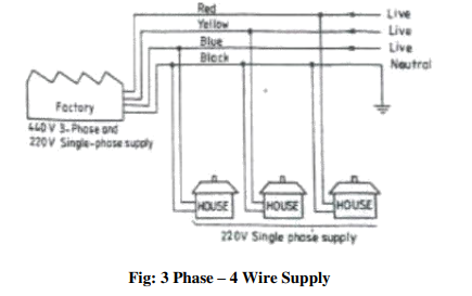
Power is supplied to domestic installations through a phase and a neutral, forming a
single phase A.C.230V, two-wire system. For industrial establishments, power is supplied
through three-phase four wire system, to give 440 V. Figure 3.1 shows the power tapping for domestic and industrial purposes. The neutral is earthed at the distribution sub-station of the supply.
When supplied to domestic utilities, power is fed to a kilowatt meter and then to a distribution panel. The panel distributes power along several circuits. It also protects these circuits from overload by safety devices like fuses or circuit breakers. The panel also serves as a main switch.
As a safety practice, all single-phase devices such as switches, fuses, etc., are connected to the live conductor. All electrical conductors and cables are color coded and must be correctly connected-up. Electrical wiring is defined as a system of electric conductors, components and apparatus for conveying electric power from the source to the point of use. The wiring system must be designed to provide a constant voltage to the load.
Elements of House Wiring:
Fuses and Circuit Breakers
These are the devices designed to provide protection to a circuit against excess current. In old type of distribution panels, open link fuses, plug or cartridge fuses were used. In newer panels, circuit breakers are used. If something goes wrong with an appliance or supply, the line becomes over loaded or short-circuited. Then, either the fuse blows-out or circuit breaker trips open, isolating that circuit or appliance. In such cases, the appliance must be checked for defects or it must be ensured that there are not too many appliances in that particular circuit.
Figure below shows several forms of fuses that are in use. Open link fuses are not safe in operation, even though they are cheaper and reliable. It consists of a thin strip of metal or wire. Here, when the fuse blows-off due to heavy current in the circuit, the metal is spilled around. A modified version of it consists of a porcelain fuse link, backing the wire safely.
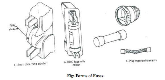
Through the plug fuse confines the molten metal thrown out while blowing, it is not very accurate in operation. The length of the element also is very short. The cartridge fuse of nonrenewable type, enclose the fuse element in a fiber tube with a non-inflammable material. During the blowing-off, the arc produced is chilled by the non-inflammable material. In case of a renewable type, a cheap renewable fuse material is used in the cartridge.
The trouble with fuses is that they must be replaced once they burn away, whereas the circuit breaker can be reset after the original condition is established. An electromagnetic circuit breaker is shown in below figure. A set of switch contacts inside the circuit breaker is normally kept closed by an armature. When too much current flows through the coil, the armature is attracted, breaking the circuit. The circuit breaker may be reset by a toggle lever.
Common House Wiring Connections:
One Lamp Controlled by a One-Way Switch
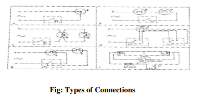
Figure (a) below shows the wiring diagram for a lamp controlled by a one-way switch. This is the normal connection one comes across in house wiring. However, more than one lamp may be connected either in series or parallel and controlled by a one way switch as shown in figures b & c respectively.
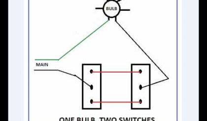
Lamp with Independent Control from Two Places
It is sometimes desirable to control from two different places .one may come across this situation with stair case, bed room, long corridors or hall containing two entrances, etc.this is achieved by two way switches as shown in fig.d.
Two Lamps Connected in Series or Parallel by a One Way Switch
Two lamps may be connected by a one way switch in parallel for bright glow or in series for dull glow .this is recommended when the intensity in the room as to be controlled (fig.e).
Tube Light Connection
Figure (f) shows a typical tube light connection. Tube lights are the commonly used light
sources for illumination in the houses, industries, commercial organizations, etc. A tube light is a low power mercury discharge lamp with internal surface coated with suitable fluorescent material. This lamp consist of a glass tube, provided at both ends with caps having two pins and oxide coated tungsten filament. The tube contains argon or krypton gas to facilitate starting with small quantity of mercury at low pressure.
Fluorescent material when subjected to electromagnetic radiations of a particular wave length produced by the discharge till mercury vapor gets excited and in turn gives out radiations at some other wave length which falls under visible spectrum. These secondary radiations from fluorescent powder increase the efficiency of the lamp. Tube lights are generally made of 20 Watt or 40 Watt rating. In order to make a tube light self starting a starter and a choke are connected in the circuit as shown in Fig. f.
When switch s1 is closed, full supply voltage induces across the starter electrodes P and Q which are enclosed in a glass bulb, filled with organ gas. This voltage causes discharge in the organ gas, resulting in the heating of the electrodes. Due to this heating, the electrode P which is made of bimetallic strip, bends closes the contact of the starter. At this stage the choke, the filaments M1 and M2 of the tube T and the starter become connected in series across the supply; causing current flow through the filaments M1 and M2 and heating them. Mean while, the argon gas discharge in the starter tube disappears causing sudden break between electrodes P and Q. This causes a high value of induced e.m.f in the choke. The induced e.m.f in the choke is applied across the tube light electrodes M1 and M2 and is responsible for initiating a gaseous discharge. Thus, the tube light starts giving light output. Once the discharge through the tube is established, a much lower voltage than the supply voltage is required to maintain it. A reduction in voltage available at the tube during running condition is achieved by having a voltage drop across the choke.
The capacitor connected across the starter terminals P and Q is used to suppress the
electromagnetic waves generated at the gap due to sparking.
Note: the wattage of the tube, choke and starter should be the same.
Earthing
The definition of the term, “earthing or grounding” as it is otherwise called, refers to the
connection of the electrically equipment to the mass of the earth by a wire of negligible
resistance for the safety of the human body from shocks. The metallic covers of the machines, the frames of the machines, sheathing of wiring, etc. are generally dead. Failure of insulation or workmanship may make these alive. When this happens, a person touching the parts receives an electric shock. To avoid this, the relevant parts are earthed. A good earthing system should have a very low resistance and should be in a position to allow the leakage current through it. The following are the methods of earthing:
a. Earthing through a water main,
b. Plate earthing, and
c. Pipe earthing
The following are the some of the items that need earthing: Metallic coverings containing
electric supply wire, switches, distribution fuse boards, ceiling fans, generator frames, stationary and portable motors, metallic parts of transformer, refrigerators, energy meters, cooking oven, electric heaters, etc.
Safe Practices
1. When closing the electric switch, always grasp the switch by the insulated handle
2. Do not run too many electrical items from one point
3. Use fuses in the circuit breakers of proper capacity, so as to interrupt the current before it becomes dangerous
4. Disconnect the units to be repaired, free from power supply and make sure that they might not be energized while the repair work continues
5. Do not pour water to put off fires in electric wires and electric equipment. You will be subjected to electric shock, or you will be electrocuted use sand to put off fires in electric items.
6. Whenever there is power failure put-off the power supply to all equipments in order to prevent spontaneous recovery
7. Never remove a plug from an outlet by pulling the cord. Always pull by the plug.
8. Never work on electric wires when the power is on
9. Never work with bare feet
10. While testing, always keep one hand in your pocket. If the hands are in contact with a circuit, a current will flow across your body and is more dangerous.
11. Electricity has no respect for ignorance. Do not apply voltage or turn-on any device until it has been properly checked.
12. Check the earth connection before switching-on portable equipment
13. Before replacing the blown fuse, always switch-off the main switch


Comments are closed.