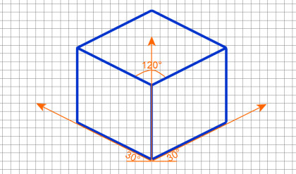
The isometric projection can be visualized is by considering a view of a cube with one of the
solid diagonals perpendicular to the vertical plane and the three axes equally inclined to the
vertical plane. The final front view is the isometric projection of the cube. Figure 15.3(a) shows
the front view when hidden lines are removed. It gives the realistic view of the cube. The
corners are renamed in capital letters. A keen study of this view reveals the following
information.
1. The outer boundary ABFGHDA is a regular hexagon.
2. All the faces of the cube which are actually square in shape appear as rhombus.
3. The three lines CB, CD and CG meeting at C, represent the three mutually perpendicular
edges of the cube.
a. They make equal angles of 120° with each other.
b. They are equal in length but smaller than the true length of the edge of the cube.
c. The line CG is vertical, and the other lines CB and CD make 30° with the horizontal.
4. All other lines representing the edges of the cube are parallel to one or the other of the above
three lines, i.e., CB, CD and CG, and are equally foreshortened.
5. The diagonal BD of the top face ABCD is parallel to V.P., and hence shows its true length.
A comparison of the rhombus ABCD of the front view with the square face of the cube is shown
in below figure.
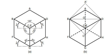
Isometric Axes, Lines and Planes
1. The three lines CB, CD, CG meeting at a point C and making an angle of 1200 with each
other are called Isometric axes.
2. The lines (AB, BF, FG, GH, DH and AD) parallel to the Isometric axis are termed as
Isometric lines.
3. The lines (BD, AC, CF, BG, etc.,) which are not parallel to the isometric axes are known
as Non-Isometric lines
4. The plane (ABCD, BCGF, CGHD, etc.,) representing any face of the cube as well as other
plane parallel to it is called an Isometric Plane.
5. The plane (ABGH, CDEF, AFH, CFH, etc.,) which is not parallel to isometric planes are
known as Non-Isometric Planes.
6. The scale which is used to convert the true length into isometric length is known as
Isometric Scale.
Isometric Scale
Referring to the above Fig., all the edges of the cube are equally foreshortened. Therefore, the
square faces are seen as rhombuses in the isometric projection. The foreshortening of the edge
can be calculated as follows:
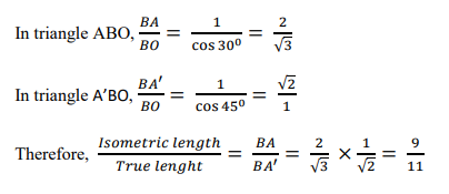
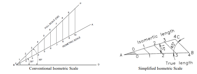
This reduction of the true length can be obtained either by multiplying it by a factor 0.816 or
by taking the measurement with the help of an isometric scale.
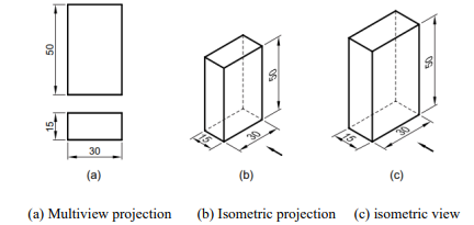
Isometric Projection and View
Isometric projection of an object is the front view of the object placed in isometric position.
Isometric projection is the actual projection of the object on V.P. Here as the edges of the
transparent cube are inclined ![]() to V.P., their projection on VP will have a length of about
to V.P., their projection on VP will have a length of about
82% of the true length, when measured in the isometric position.
Isometric projection can be drawn directly, using the true length of the dges of the cube along
the isometric axes. As a result, the projection obtained is larger in size than the actual. This
projection is called isometric View or Isometric Drawing.
Dimensioning
The general rules for the dimensioning of multi view projection is applicable for isometric
projection, except the following:
1. All the extension lines and dimension lines should be parallel to the isometric axes and
they should be on any of the isometric planes.
2. The text should be placed at the middle of the dimension line, after breaking it to a short
length.
3. The dimensional values in X direction should be readable from the right side. While the
Y direction from left side and Z direction from the right side respectively.
4. The numerals placed along the three axes should be aligned with the direction of the
axes.
System of Notation
1. The actual solid in space is denoted by capital letters A1 , B1, C1 and D1 etc for Base of
solid and A, B, C and D etc for top face of the solid and axis as o1 and o.
2. The front view (FV) of a solid is denoted by their corresponding lower case letters with
dashes as a1′, b1′, c1′ and d1′ etc for base of solid and a’, b’ c’ and d’ etc for top face of the
solid and for axis as o1′ and o’.
3. The top view (TV) of a solid is denoted by their corresponding lower case letters with
dashes as a1, b1, c1 and d1 etc for bottom of solid and a, b c and d etc for top face of the
solid and for axis as o1 and o.
4. Projectors are always drawn as continuous thin lines.
5. Isometric projection annotations are made with the corresponding letters of the solid.
6. Line with specific thickness for a particular type of line.

Comments are closed.