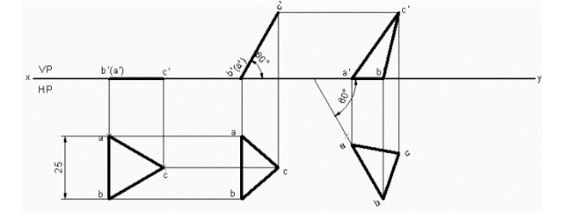
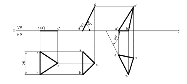
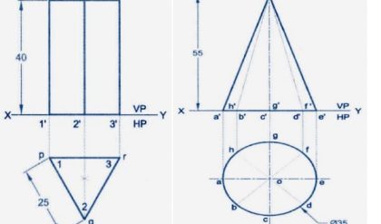
1. An equilateral triangular lamina of 25 mm side lies with one of its edges on HP such that the surface of the lamina is inclined to HP at 60º. The edge on which it rests is inclined to VP at 60º. Draw the projections.
Solution
1. Open the Software. Click on the Application Menu and click on New and select “acad “in the
open dialog box and click Open.
2. Enter the command “UNITS “in command bar and Select units as “Millimeters and click ok.
3. Enter the command “LIMITS “in command bar and enter 0,0 click enter and enter upper right
corner as 120,90 and click enter
4. Enter the command “ZOOM “in command bar and enter A and click enter
5. Draw a XY line by using line command. Mark VP and HP above and below it by using
“XTEXT” command in command bar
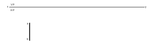
6. As per the problem equilateral triangular lamina of 25mm has to be drawn in HP, hence draw
a vertical line of 25 mm using POLYLINE command and in format select VL and enter length
as 25 and angle as –90 in mini dialog box. Mark annotations a and b using XTEXT Command
as shown below.
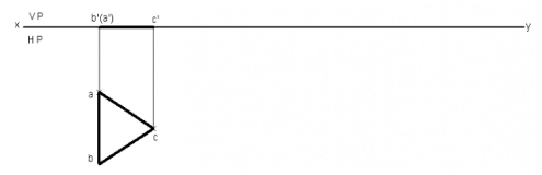
7. Draw an arc of radius of 25 from a and b to cut each other at c using CENTER CIRCLE
command in drafting tool bar and in format select PL. In mode option select arc. Join abc to
get triangular lamina of 25 mm using POLYLINE command
8. Draw front view of the triangular lamina using POLYLINE command and in format select
VL, mark annotations as (a’) b’ and c’ as shown below.
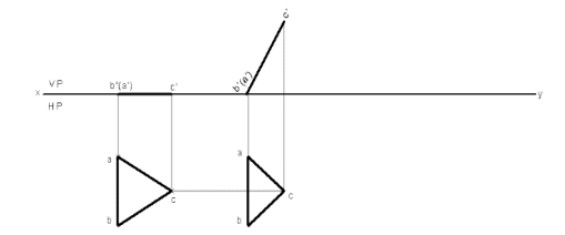
9. Since the lamina is inclined at 60° to HP. By using POLYLINE command and in format select
VL enter length equal to length of first stage front view and angle as 60 in mini dialog box,
mark annotations as (a’) b’ and c’ using XTEXT Command
10. Draw vertical projectors downwards from the second front view using POLYLINE command
and in format select PL. Draw horizontal projectors from top view to intersect vertical
projectors at a, b and c which forms the second stage top view as shown below.
11. Since the edge on which it rests is inclined to VP to 60° Draw a line of 60° in HP using
POLYLINE command and in format select PL. From edit menu select MOVE COPY
command and then select second stage top view. In selection tree right click on the start point
and click reset to select the start point anywhere on the edge of lamina to shift on to 60° line
drawn. Click and drag the lamina on 60° line. Click or drag to rotate and enter angle as 30 in
mini dialog box and click on OK
12. Draw the vertical projection upwards from all the corners of triangular lamina from third stage
top view using POLYLINE command and in format select PL. Again, draw horizontal
projectors from second stage front view to intersect vertical projectors at a’ b’ and c’.
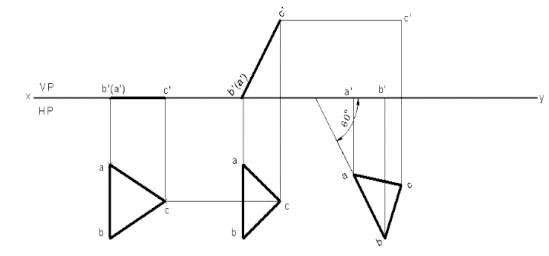
13. Join a’ b’ and c’ using POLYLINE Command
14. Using DIMENSION Command in Annotation tool bar or Enter DIM command in command
bar dimension the drawing
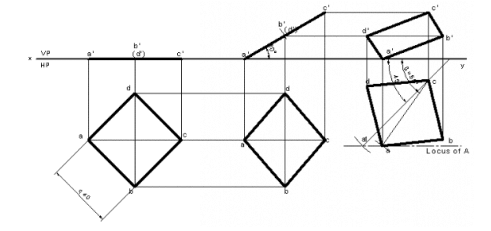
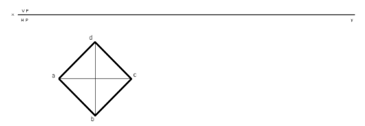
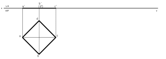
2. A square plate of 40 mm side rests on HP such that one of the diagonals is inclined at 30º to HP and 45º to VP. Draw its projections.
Solution
1. Open the Software. Click on the Application Menu and click on New and select “acad “in the
open dialog box and click Open.
2. Enter the command “UNITS “in command bar and Select units as “Millimeters and click ok.
3. Enter the command “LIMITS “in command bar and enter 0,0 click enter and enter upper right
corner as 100,100 and click enter
4. Enter the command “ZOOM “in command bar and enter A and click enter
5. Draw a XY line by using line command. Mark VP and HP above and below it by using
“XTEXT” command in command bar.
6. As per the problem a square lamina of 40 mm has to be drawn in HP, hence draw a square of
40 mm using RECTANGLE command Now enter X size = 40, Y size = 40 and angle as 45 in
mini dialog box. Mark annotations a b c and d using XTEXT Command as shown below.
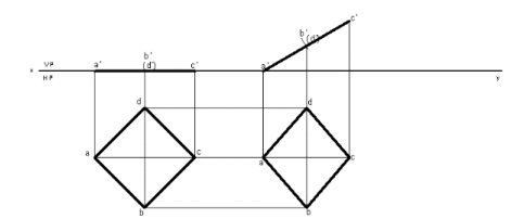
7. Draw the vertical projection upwards from all the corners of square lamina in top view until it
touches XY line, using POLYLINE command and in format select PL.
8. Draw front view of the triangular lamina using POLYLINE command and in format select VL,
mark annotations as a’ b’ c’ and (d’) as shown below.
9. Since the diagonal of lamina is inclined at 30° to HP. By using POLYLINE command and in
format select VL enter length equal to length of first stage front view and angle as 30 in mini
dialog box, mark annotations as a’ b’ (d’) and c’ using XTEXT command
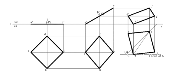
10. Draw vertical projectors downwards from the second front view using POLYLINE command
and in format select PL. Draw horizontal projectors from top view to intersect vertical
projectors at a, b c and d which forms the second stage top view as shown below.
11. Since the diagonal of lamina is inclined to VP at 45°. Draw a line of 45° in HP using
POLYLINE command and in format select PL. Draw an arc of radius equal to diagonal length
of lamina from first stage top view to cut on 45° line drawn. Draw a locus from point a1, now
with radius equal to diagonal length of lamina from second stage top view to cut on the locus.
Join ac to get the diagonal of third stage top view. From edit menu select MOVE command
and then select second stage top view. In selection tree right click on the start point and click
reset to select the start point anywhere on the diagonal of lamina to shift on to new diagonal
line drawn. Click and drag the lamina on new diagonal line. Click or drag to rotate and enter
angle so as to match both diagonals and click on OK. Mark annotations as a b c and d.
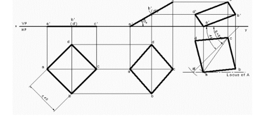
12. Draw the vertical projection upwards from all the corners of square lamina from third stage
top view using POLYLINE command and in format select PL. Again, draw horizontal
projectors from second stage front view to intersect vertical projectors at a’ b’ c’ and d’.
13. Join a’ b’ c’ and d’ using LINE Command and in format select VL.
14. Using DIMENSION Command in Annotation tool bar or Enter DIM command in command bar dimension the drawing
Comments are closed.