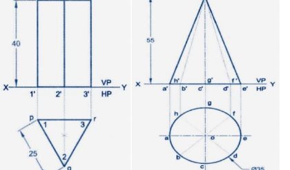
In engineering drawing, orthographic projection of a solid is best way of projecting the details
of an object when a solid is resting in its simple position. As the front view or top view taken
separately, gives an incomplete idea of the object, a pictorial projection is the best method to
show the object in one view only. Basically, pictorial projection represents three dimensional
shape of an object and represents real things in one view only, which indicates length, breadth
and height of the object. Therefore, the object is easily visualized from a pictorial projection
than from its orthographic projection.
The pictorial projection may be divided as:
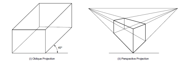
1. Oblique projection
2. Perspective projection
3. Axonometric projection.
Axonometric Projection
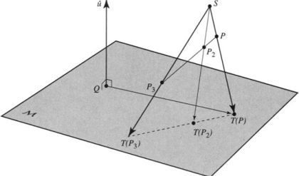
An axonometric projection is a type of single-view parallel projection used to create a pictorial
drawing of an object. The object is placed in such a position that the three mutually
perpendicular faces are visible from a single direction. The word ‘axonometric projection’
means measuring along axis in which “axon” means axis while metron means measuring.
Axonometric projections are commonly used to draw mechanical parts of an object for the clear
picture of an object which are visualized from the orthographic projection. In this projection
the object can be drawn at different angles and having the different length of edges.
Axonometric projections are again classified as:
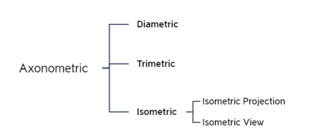
Trimetric Projection
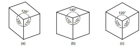
In this type, an object is placed in such a way that no two axes make an equal angle with the
plane of projection.
Dimetric Projection
In this type of projection, an object is placed in such a way that two of its axes make equal
angle with the plane of projection and the third axis makes either a smaller or a greater angle.
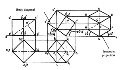
Isometric Projection
In this type of projection, an object is placed in such a way that all three axes make equal angle
with the plane of projection.
The isometric projection is the most common pictorial representation used in industries where
visualization of the three dimensions of a solid are not only shown in one view, but their actual
sizes can be measured directly from it. As it shows views of three faces of an object equally, it
is very helpful to even a layman to understand the shape of the object. A multiview drawing
requires two or more orthographic projections to define the exact shape of a three dimensional
object. Each orthographic view is a two-dimensional drawing showing only two out of three
dimensions of the object.

Comments are closed.