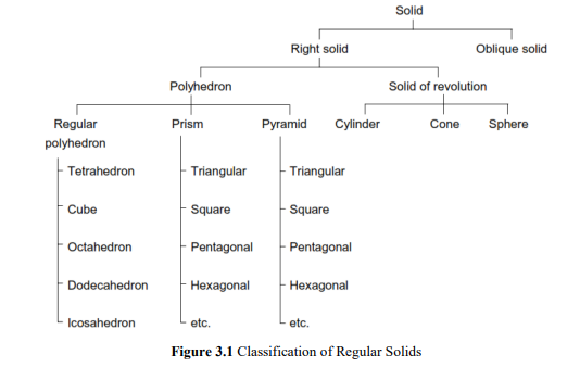
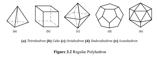
Polyhedron
A polyhedron is a solid bounded by planes called faces, which meet in straight lines called
edges. A regular polyhedron has all the faces equal and regular as shown in Fig. 3.2.
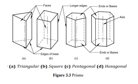
Prism
A prism is a polyhedron with two n-sided polygonal bases which are parallel and congruent,
and lateral faces are rectangles. All cross-sections parallel to the bases are congruent with the
bases. An imaginary line that joins the centre of the bases is called an axis. A right and regular
prism has regular polygonal bases, axis perpendicular to the bases and all the faces are equal
rectangles, as shown in Fig.3.3. Prisms are named according to the shape of their base, so a
prism with a triangular base is called a triangular prism; a square base is called a square prism
and so on.
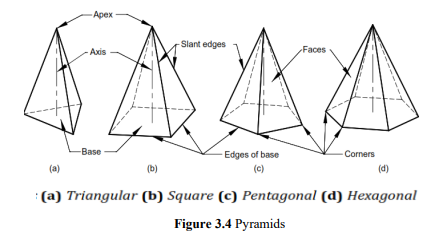
Pyramid
A pyramid is a polyhedron with n-sided polygonal base and lateral faces are triangles meeting
at a point called the vertex or apex. An imaginary line that joins the apex with the centre of the
base is known as the axis. A right and regular pyramid has a regular polygon base, axis
perpendicular to the base and all the faces are equal isosceles triangles, as shown in Fig. 3.4.
Pyramids are named according to the shape of their base, so a pyramid with a triangular base
is called a triangular pyramid; a square base is called a square pyramid and so on. The centre
of gravity of pyramids lies on the axis at one-fourth of its height from the base.
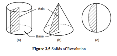
Solid of Revolution
These solids are obtained by revolving a plane figure like rectangle, triangle or a semi-circle
about a fixed line.
Cylinder: A cylinder is a solid of revolution obtained by revolving a rectangle about one of its
fixed side called an axis. It can be imagined as a prism of infinite number of lateral faces. Any
line on the surface of a cylinder is called its generator. Thus, a cylinder has an infinite number
of generators. A right cylinder has all the generators and the axis perpendicular to the base, as
shown in Fig. 3.5(a).
Cone: A cone is obtained by revolving a triangle about its fixed side called an axis. A cone can
be imagined as a pyramid with infinite number of lateral faces. Any line on the surface of a
cone is called its generator. Thus, a cone has an infinite number of generators. A right cone has
all generators of equal length and the axis perpendicular to the base, as shown in Fig. 3.5(b).
Sphere: A sphere is obtained by revolving a semi-circle around its diameter, as shown in Fig
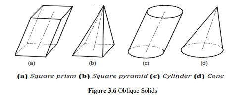
Oblique Solid
An oblique solid such as oblique prism, pyramid, cylinder or cone has its axis inclined to its
base as shown in Fig.3.6. The faces of an oblique prism are parallelograms of different sizes.
The faces of an oblique pyramid are triangles of different sizes. The generators in an oblique
cylinder have equal lengths whereas those in an oblique cone have unequal lengths.
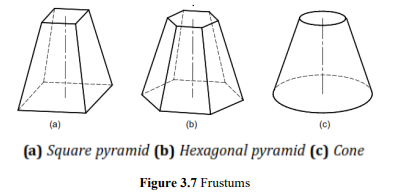
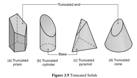
Frustum of Pyramid and Cone
When a regular pyramid or a cone is cut by a plane parallel to its base and the portion of the
solid containing apex is removed, the remaining portion of the solid is called the frustum of
that pyramid or cone, as shown in Fig. 3.7.
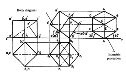
Recommended Method of Labelling
It is recommended to label the corners of the solids in a manner as shown in Fig. 3.8.
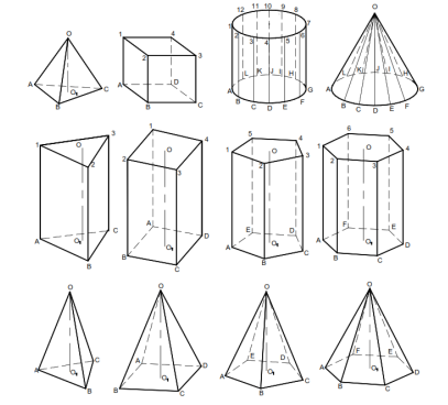
Figure 3.8 Method of Labelling
Positions of Solids
The position of a solid in space is specified by the inclinations of its axis with the RPs.
Therefore, a solid will have positions with respect to RPs same as that of a line. Depending on
the orientation of its axis in space, a solid may have the following positions:
The solid may be in one of the following positions:
1. Axis perpendicular to the H.P.
2. Axis perpendicular to the V.P.
3. Axis parallel to both the H.P. and the V.P. (i.e., perpendicular to the profile plane)
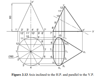
4. Axis inclined to the H.P. and parallel to the V.P.
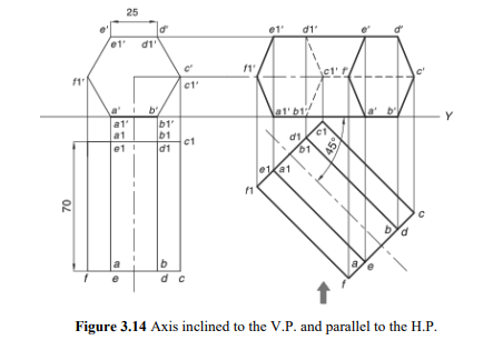
5. Axis inclined to the V.P. and parallel to the H.P.
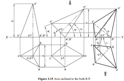
6. Axis inclined to both the H.P. and the V.P.
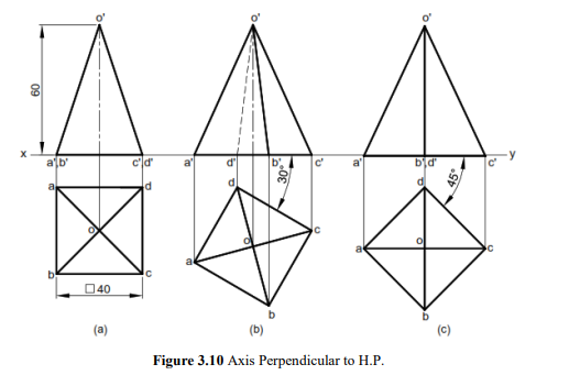
Axis Perpendicular to H.P
This is one of the basic positions of the solid. It is evident that if the axis of a right solid is
perpendicular to the H.P., its base will be parallel to the H.P. The true shape and size of the
base can be viewed in the top view. Therefore, first obtain the top view of the solid and then
project it to obtain the front view.
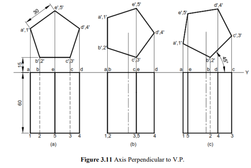
Axis Perpendicular to V.P.
This is one of the basic positions of the solid. It is evident that if the axis of a right solid is
perpendicular to the V.P., its base will be parallel to the V.P. The true shape and size of the
base can be viewed in the front view. Therefore, first obtain the front view of the solid and then
project it to obtain the top view.
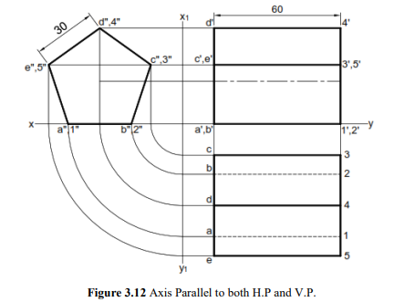
Axis Parallel to both H.P. and V.P.
It is evident that if the axis of right solids is parallel to both H.P. and V.P., the base of the solid will be perpendicular to the reference planes and parallel to the profile plane. The true shape and size of the base can be viewed in the side view. Therefore, first obtain the side view of the solid and then project it to obtain the front and the top views.
Axis inclined to the R.P. and parallel to the R.P.
If the axis of a solid is inclined to one RP and parallel to the other RP then the problem is solved in two stages. In the first stage, the axis is assumed to be perpendicular to the RP to which it is finally inclined. The view obtained on that RP will give the true shape of the base. The corresponding other view will give the TL of the axis. In the second stage, the other view is redrawn in such a way that the axis will make the required angle with the given RP. Here, it should be noted that the inclination of the axis with a particular RP might not be given directly. Instead, it may be expressed in terms of other parameters, as mentioned earlier.
Axis inclined to the both R.P ‘S.
If the axis of a solid is inclined to both the RPs then the problem is solved in three stages. As
already mentioned, the inclinations of the axes may not be given directly. Instead, it may be
indirectly mentioned by means some other parameters. If the inclinations are given directly
then, in the first stage, the axis is assumed to be perpendicular to any one RP. The view obtained
on that RP will give the true shape of the base. The corresponding other view will give the TL
of the axis. In the second stage, the other view is redrawn so that the axis will make the required
angle with the RP to which it was initially perpendicular. The corresponding next view is
obtained in the second stage. In the third stage, the next view is redrawn so as to make the
‘desired inclination’ of the axis with the other RP. Here, the ‘desired inclination’ is the apparent
inclination of the axis which is obtained by using the theory of projections of the lines. The
view thus obtained satisfies all the conditions, i.e., inclinations with both the RPs, and hence
represents the final view. This view is then projected to obtain the other corresponding final
view.
If the inclinations are not given directly then the first stage must be decided carefully. Often an
inclination of the axis with one RP is given and the inclination with the other RP is given in
terms of the inclination of an edge or face of the solid. In such a case, the first stage is to keep
the axis perpendicular to that RP with which its inclination is known. In the second stage, the
required inclination with that RP is obtained. In the third stage, the other condition, viz.,
inclination of the face or inclination of an edge, is established. It must be remembered that, in
the first stage, the solid is always kept in such a way that the true shape of the base and TL of
the axis are visible. This helps to satisfy the condition on the axis (mentioned directly or indirectly) easily in the second stage. Note that one view in the second stage always gives TL of the axis (since it is simply redrawn from the first stage).
Other possibilities are explained with the help of examples.

Comments are closed.