In Computer Aided Engineering Graphics for isometric projections following commands are
used other than evoking software, opening file, saving file and giving print command. A 2D
isometric drawing is a flat representation of a 3D isometric projection. This method of drawing
provides a fast way to create an isometric view of a simple design. Distances measured along
an isometric axis are correct to scale, but the 3D distances and areas cannot be extracted since
the drawings will be in 2D, display objects from different viewpoints, or remove hidden lines
automatically.
By using the ISODRAFT command, several system variables and settings are automatically
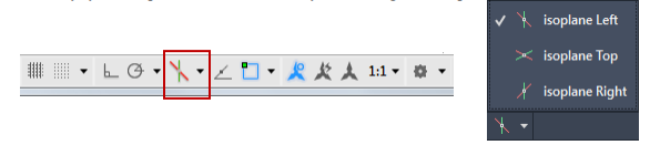
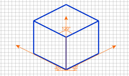
changed to values that facilitate isometric angles. Isoplane specifies the current isometric plane.
The standard isometric planes, called isoplanes, are as follows:
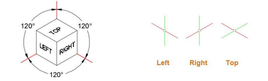
· Right.: Selects the right-hand plane, defined by the 30- and 90-degree axes pair
· Left: Selects the left-hand plane, defined by the 90- and 150-degree axes pair.
· Top: Selects the top face, called the top plane, defined by the 30- and 150-degree axis pair.
You can use the Isometric Drafting tool on the status bar to select the desired isoplane.
Alternatively, you can press F5 or Ctrl+E to cycles through the isoplanes.
Using these following commands and features are the most commonly used ones to maintain
precision in isometric drawings:
· Polar tracking and direct distance entry
· Object snaps and grid snaps
· Object snap tracking
· Move and Copy
Extrude
The EXTRUDE command creates a solid or surface that extends the shape of a curve. Open
curves create surfaces and closed curves create solids or surfaces
When you extrude objects, you can specify any of the following options:
Mode. Sets whether the extrude creates a surface or a solid.
Specify a path for extrusion. With the Path option, create a solid or surface by specifying an
object to be the path for the profile, or shape, of the extrusion. The extruded object starts from
the plane of the profile and ends on a plane perpendicular to the path at the endpoint of the path.
For best results, use object snaps to make sure that the path is on or within the boundary of the
object being extruded.
Taper angle. Tapering the extrusion is useful for defining part that require a specific taper
angle, such as a mold used to create metal products in a foundry.
Direction. With the Direction option, you can specify two points to set the length and direction
of the extrusion.
Expression. Enter a mathematical expression to constrain the height of the extrusion.
Revolve
Open profiles create surfaces and closed profiles can create either a solid or a surface. The
MOde option controls is a solid of surface is created. When creating a surface,
SURFACEMODELINGMODE system variable controls if a procedural or NURBS surface is
created.
Revolve path and profile curves can be:
· Open or closed
· Planar or non-planar
· Solid and surface edges
· A single object (to extrude multiple lines, convert them to a single object with the JOIN command)
· A single region (to extrude multiple regions, first convert them to a single object with the UNION command)
The following are the options for revolving:
Objects to Revolve
Specifies the objects to be revolved about an axis.
Mode
Controls whether the revolve action creates a solid or a surface. Surfaces are extended as either
NURBS surfaces or procedural surfaces, depending on the SURFACEMODELINGMODE
system variable.
Axis Start Point
Specifies the first point of the axis of revolution. The positive axis direction is from the first to
the second point.
Axis Endpoint
Sets the endpoint for the axis of revolution.
Start Angle
Specifies an offset for the revolution from the plane of the object being revolved.
Angle of Revolution
Specifies how far the selected object revolves about the axis.
Loft
Creates a 3D solid or surface by specifying a series of cross sections. The cross sections define
the shape of the resulting solid or surface. Loft cross sections can be open or closed, planar or
non-planar, and can also be edge subobjects. Open cross sections create surfaces and closed
cross sections create solids or surfaces, depending on the specified mode.
The following prompts are used under loft:
Cross Sections in Lofting Order
Specifies open or closed curves in the order in which the surface or solid will pass through
them.
Point
Specifies first or last point of the lofting operation. If you start with the Point option, you must
next select a closed curve.
Join Multiple Edges
Handles multiple, end-to-end edges as one cross section.
Mode
Controls whether the lofted object is a solid or a surface.
Continuity
This option only displays if the LOFTNORMALS system variable is set to 1 (smooth fit).
Specifies whether the continuity is G0, G1, or G2 where the surfaces meet.
Bulge Magnitude
This option only displays if the LOFTNORMALS system variable is set to 1 (smooth fit).
Specifies a bulge magnitude value for objects that have a continuity of G1 or G2.
Guides
Specifies guide curves that control the shape of the lofted solid or surface. Guide curves can be
used to control how points are matched up on corresponding cross sections to prevent undesired
results, such as wrinkles in the resulting solid or surface.

Comments are closed.