Projection of Planes
Introduction
A plane is a two-dimensional geometrical entity. It has length and width but no thickness. For
practical purposes, a flat face of an object may be treated as a plane. A plane which has limited
extent is termed as a lamina.
A plane can be located by:
(i) Three non-collinear points,
(ii) A straight line and a point outside it,
(iii) Two parallel or intersecting straight lines, or
(iv) Traces of the lines.
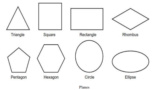
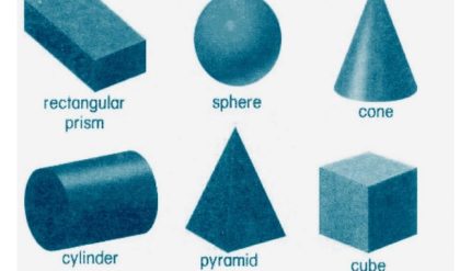
This chapter deals with the projections of laminas of pre-defined shapes, e.g., triangular plane,
square plane, rectangular plane, pentagonal plane, hexagonal plane, circular plane, semicircular
plane, etc. Sometimes, a given plane is composed of two or more planes mentioned above. Such
planes are called composite planes, e.g., plane composed of a half hexagon and a semicircle,
circular plane with hexagonal hole, etc.
Positions of Planes
1. Plane parallel and perpendicular to reference planes (HP & VP)
A. Plane parallel to HP and perpendicular to VP.
B. Plane parallel to VP and perpendicular to HP.
2. Plane perpendicular and inclined to reference planes (HP & VP)
A. Plane perpendicular to HP and inclined to VP.
B. Plane perpendicular to VP and inclined to HP.
3. Plane perpendicular to both HP & VP.
4. Plane inclined to both HP & VP
A. Inclination to HP and VP is not equal to 90°.
B. Inclination to HP and VP is equal to 90°.
Terms Used in Projections of Planes
The following terms must be understood before we proceed for the step-by-step procedure of
obtaining the projections of a plane.
True Shape: The actual shape of a plane is called its true shape.
Inclination with the RPs: The inclination of a plane with an RP is the acute angle the plane makes
with that RP. It is always measured in a plane perpendicular to the given plane and the RP.
Inclination with the HP (θp) It is the acute angle the plane makes with the HP.
Inclination with the VP (ϕp) It is the acute angle the plane makes with the VP.
Traces of the Plane: Just like a line, a plane also has traces. The traces of a plane are the lines of
intersections of the plane with the RPs. A plane may have a horizontal trace or vertical trace or
both.
Horizontal Trace (HT) The real or imaginary line of intersection of a plane with the HP is
called horizontal trace of the plane. HT is always located in the TV.
Vertical Trace (VT) The real or imaginary line of intersection of a plane with the VP is
called vertical trace of the plane. VT is always located in the FV.
It should be noted that the plane has no trace on the RP to which it is parallel. For example, a plane
parallel to the HP will have no HT. Similarly, a plane parallel to the VP will have no VT. HT and
VT of a plane (produced if necessary) meet at a point on the XY.
Perpendicular Planes: The planes perpendicular to one or both the RPs are called perpendicular
planes. The first three positions of the planes mentioned in the previous section represent
perpendicular planes.
Oblique Planes: The planes inclined to both the RPs are called oblique planes. The fourth position
of the planes mentioned in the previous section represents oblique planes.
Line View or Edge View: The view of a plane seen as a line is called line view or edge view of the
plane. One view of a perpendicular plane is always an edge view. The edge view always represents
the trace of the plane. For example, if a plane is perpendicular to the VP, then its FV will be an
edge view representing VT of the plane. Similarly, TV of a plane perpendicular to the HP Will be
an edge view representing HT.
System of Notation
1. The actual plane in space is denoted by capital letters A, B, C and D etc.
2. The front view (FV) of a plane is denoted by their corresponding lower-case letters with
dashes as a’, b’, c’ and d’ etc.
3. The top view (TV) of a plane is denoted by their corresponding lower-case letters without
dashes as a, b, c and d etc.
4. The side view (SV) of a plane are denoted by their corresponding lower-case letters with
double dashes as a”, b”, c” and d” etc.
5. Projectors are always drawn as continuous thin lines.
6. Line with specific thickness for a particular type of line.
In Computer Aided Engineering Graphics for projection of plane following commands are used
other than evoking software, opening file, saving file and giving print command. Using these
minimum12 commands any type of projection of line problem can be solved they are as follows:
1. Select tool Command.
2. Point command.
3. Poly-Line command.
4. Two Point Line command.
5. Parallel line command.
6. Center Circle command
7. Bisector command.
8. Smart Dimension command
9. Line Width command
10. Insert Text command.
11. Move Copy command.
12. Rectangle command.
Plane parallel and perpendicular to reference planes (HP & VP)
If the given plane is parallel to an RP, it remains perpendicular to the other RP. In such a case, the
view of the plane on the RP to which it is parallel gives the true shape. Another view is always an
edge view parallel to XY.
Plane parallel to HP and perpendicular to V
If a plane is parallel to the HP, its TV gives the true shape. Therefore, TV should be drawn first.
FV will be an edge view parallel to XY. SV will be perpendicular to X Y.
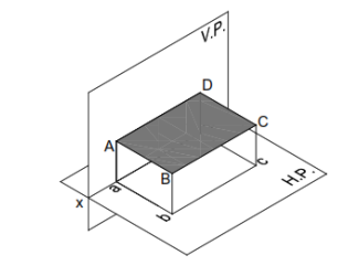
Plane parallel to HP and perpendicular to VP.
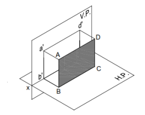
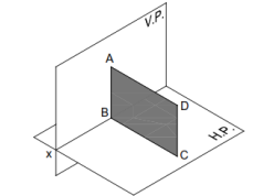
Plane parallel to VP and perpendicular to HP
If a plane is parallel to the VP, its FV gives the true shape. Therefore, FV should be drawn first.
TV will be an edge view parallel to XY. SV will be perpendicular to X Y.
Plane Inclined to one RP and Perpendicular to the other RP
If a plane is inclined to one RP and perpendicular to the other RP, none of its views will give the
true shape. The view on the RP to which the plane is inclined will be smaller than the actual size
of the plane. The view on the RP to which the plane is perpendicular will be a line view. Such
problems can be solved in two stages. In the first stage, the given plane is assumed to be parallel
to the RP to which it is finally inclined. The true shape can thus be obtained in one view. In the
second stage, another view (which is an edge view parallel to XY) is tilted so as to make desired
inclination with the first RP.
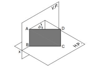
Plane Inclined to the HP and Perpendicular to the VP
When the surface of the plane is inclined at θ to the H.P. and perpendicular to the V.P., the
projections are obtained in two stages. In the first stage, the plane is assumed to lie on the H.P.
The true shape of the plane is viewed in the top view and a straight line lying on xy in the front
view. In the second stage, the plane is tilted at θ to the H.P. The front view is redrawn inclined at
θ to the xy. The final top view is obtained by joining the points of intersection of the vertical
projectors of the corners from the front view with the horizontal projectors of the corners from the
top view of the preceding stage.
Note 1 If the plane has a side on the H.P. (or parallel to the H.P. or on the ground), then keep an
edge of the plane perpendicular to xy in the top view of the first stage.
Note 2 If the plane has a corner in the H.P. (or on the ground), then keep the line joining a corner
and the centre of the plane parallel to xy.
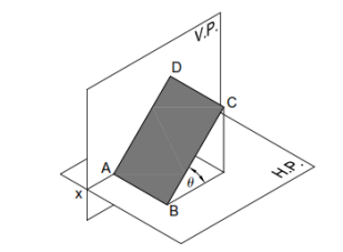
Plane Inclined to the HP and Perpendicular to the VP
Plane Inclined to the VP and Perpendicular to the HP
When the surface of the plane is inclined at ϕ to the V.P. and perpendicular to the H.P., the
projections are obtained in two stages. In the first stage, the plane is assumed to lie on the V.P.
The true shape of the plane is viewed in the front view and a straight line lying on xy in the top
view. In the second stage, the plane is tilted at ϕ to the V.P. The top view is redrawn inclined at ϕ
to the xy. The final front view is obtained by joining the points of intersection of the vertical
projectors of the corners from the top view with the horizontal projectors of the corners from the
front view of the preceding stage.
Note 1 If the plane has a side on the V.P. (or parallel to the V.P. or on the ground), then keep an
edge of the plane perpendicular to xy in the front view of the first stage.
Note 2 If the plane has a corner in the V.P. (or on the ground), then keep the line joining a corner
and the centre of the plane parallel to xy in the front view of the first stage.
Plane Inclined to the VP and Perpendicular to the HP
Plane perpendicular to both HP & VP
If a plane is perpendicular to both the RPs, then its FV and TV both will be seen as edge views perpendicular to XY. Such a plane is parallel to the PP and hence its true shape is seen in SV. Therefore, for such problems, it is advisable to draw SV first.
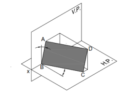
Plane inclined to both HP & VP
A plane inclined to both the RPs is called an oblique plane. None of the views of the oblique plane
gives the true shape. It should be noted that the angles made by the oblique plane with the RPs
(i.e., θ and ϕ) might not be directly given in the problem. Often, either of the inclinations, θ or ϕ,
is given along with some other condition(s) that automatically pose the restriction on the other
inclination.
The problems on oblique planes are solved in three stages. In the first stage, the plane is often
assumed to be parallel to one of the RPs so that the true shape can be obtained in one view. In the
second stage, the given angle between the plane and the RP (i.e., either the HP or the VP) or some
other condition mentioned in the problem is established. In the third stage, all other remaining
conditions are satisfied.
Plane Inclined to both HP & VP
Comments are closed.