Projections
Projection
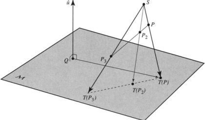
As per the optical physics, projection is a process of causing an image by rays of light taken in a
particular direction from an object to a picture plane. The imaginary ray of light between the object
and the projection plane is called line of sight or projector.
Orthographic Projection
In orthographic projection, the projectors are parallel and perpendicular to the plane of projection.
Orthographic projections on mutually perpendicular projection planes will fully describe the object
in its shape and size. Hence, all design and manufacturing drawings are made with orthographic
projections.
Projectors ⊥ to the Projection plane
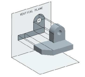
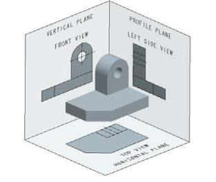
Vertical Plane and Front Elevation
A view looking from the front is projected onto the vertical plane. This view is called front view
or front elevation and shows the width and height dimensions. A vertical plane of projection, which
is behind the object in relation to the observer, is shown
in figure below.
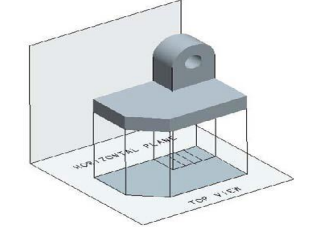
Horizontal Plane and Top View
A view looking from the top is projected onto the horizontal plane placed below the object. This view is called top view or plan. Top view shows the width and depth dimensions of an object. A horizontal plane with a top view is shown in figure below.
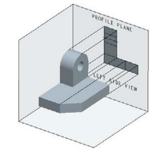
Profile Plane and End View
A view looking from the side of an object is projected onto the profile plane. The observer and the projection plane are on different sides of the object (i.e.) the object is between the observer and the projection plane. The viewing can be from the right or the left side of the object. The view drawn looking the object from the right is called right side view or right end elevation. The view looking the object from the left is called left side view or left end elevation. Side view of an object shows the depth and height dimensions. A profile plane with a left side view is shown in figure below.
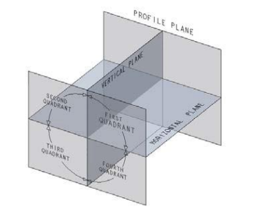
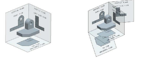
First Angle Projection
An arrangement of vertical, horizontal, and profile planes and quadrants used to draw first angle projections is shown below. Front view is projected onto the vertical plane, top view onto the horizontal plane, and side view onto the profile plane.
Projection in First Angle
An object placed in the first quadrant. The vertical plane is behind the object, horizontal plane below the object, and profile plane to right of the object. The views with the corresponding planes are shown in figure. The top view is seen below the elevation and left side view is seen on the right of front view. This is the arrangement of views in the first angle projection.
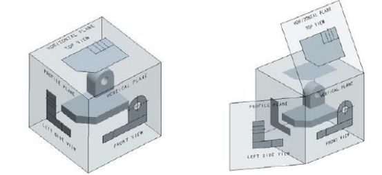
Projection in Third Angle
An object placed in the third quadrant. The vertical plane is in front of the object, horizontal plane above the object and profile plane to the left of the object. The views with corresponding planes are shown in figure. Top view is above the front view and left side view is to the left of the front view. This is the arrangement of the views in third angle projection.
Multiview Projection
It consists of a set of two or more orthographic views of an object taken from different directions, which are mutually perpendicular. These views are arranged relative to each other in a particular way. Each of these views shows the shape of the object for a particular view direction. Multiple views collectively describe the object completely and exactly. Hence, multiview projections are used in engineering to describe the true shape of any object
Comments are closed.