Point
A point usually represented by a dot is a dimensionless geometrical entity that has a position but
no magnitude. Whereas in computer aided engineering drawing the point has dimension but it is
not considered or neglected. A point is obtained wherever two straight or curved lines intersect
each other.
Projection of Points
Projection of points in various quadrants is the basis for projection of lines, projection of planes
and projection of solids. In a conventional coordinate system, the position of a point in space is
denoted by its three coordinates i.e., x, y and z.
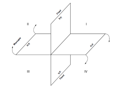
In projections, two principal planes are used to get the projection of an object that is vertical plane
and horizontal plane, the vertical plane denoted by (V.P.) and horizontal plane denoted by (H.P.)
as shown in Fig. They intersect each other at right angles and the line of intersection is known as
axis of the plane. The vertical plane of projection is always infront of the observer and the
projection on this plane is known as front view or elevation. The other plane is the horizontal plane
of projection and the projection on this plane is called the top view or plan.
Pictorial view of Principal Planes
The view obtained by viewing object form right side is called right side view or right end view. A plane perpendicular to both H.P. and V.P. is called profile plane (P.P). The right side view is always on the right to the front view. If the object is viewed from left on profile plane then the view is known as left side view or left end view.
Position of Points in Various Quadrants
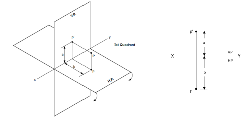
1. When point is in First Quadrant
When a Point P is situated in I quadrant i.e., above H.P. and in front of V.P. , Its front view
(p’) will be above XY line and its top view (p) will be below the XY line.
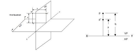
2. When point is in Second Quadrant
When a Point P is situated in II quadrant i.e., above H.P. and behind V.P. , Its front view (p’) will be above XY line and its top view (p) will also be above the XY line.
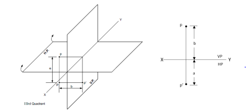
3. When point is in Third Quadrant
When a Point P is situated in III quadrant i.e., below H.P. and behind of V.P. , Its front view
(p’) will be below XY line and its top view (p) will be above the XY line.
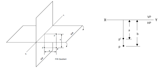
4. When point is in Fourth Quadrant
When a Point P is situated in IV quadrant i.e., below H.P. and infornt V.P. , Its front view (p’)
will be below XY line and also its top view (p).
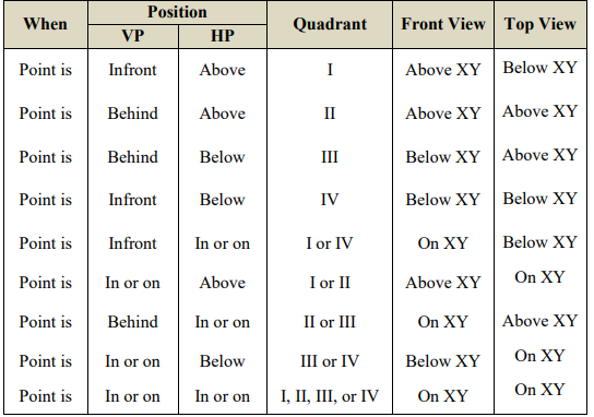
Positions of geometrical entities in various quadrants of the projections
System of Notation
1. The actual points in space are denoted by capital letters A, B, C etc.
2. The front view (FV) of the points are denoted by their corresponding lower-case letters with
dashes as a’, b’, c’, etc.
3. The top view (TV) of the points are denoted by their corresponding lower-case letters without
dashes as a, b, c etc.
4. The side view (SV) of the points are denoted by their corresponding lower-case letters with
double dashes as a”, b”, c” etc.
5. Projectors are always drawn as continuous thin lines and Points with Dot.
In Computer Aided Engineering Graphics for projection of points following commands are used
other than evoking software, opening file, saving file and giving print command. Using these
minimum nine commands any type of projection of point problem can be solved they are as
follows:
1. Select tool Command.
2. Point command.
3. Poly-line command.
4. Two point line command.
5. Parallel line command.
6. Bisector command.
7. Smart dimension command.
8. Line width command.
9. Insert text command.
Comments are closed.