1. Limits
Drawing limits are used to set the boundaries of the drawing. The drawing boundaries are
usually set to match the size of a sheet of drawing paper. This means that when the drawing is
plotted and a hard copy is made, it will fit on the drawing paper.
Command: Limits
Specify lower left corner or [ON/OFF] <0,0>: Specify a point
Specify upper right corner or <12,9>: Specify a point
Note: Limits has no limit, it can be infinity with respect to paper size
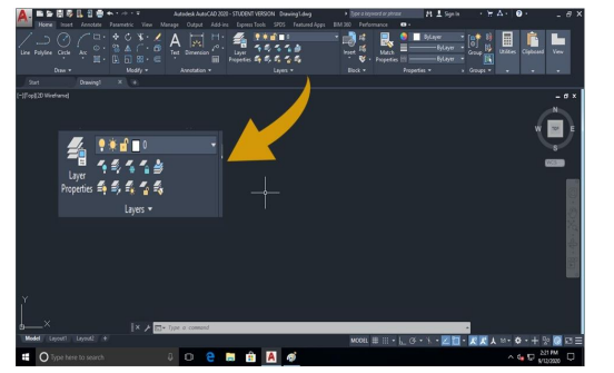
2. Layers
A layer is like a clear piece of paper that can be laid directly over the drawing. We can draw
on the layer and see through it to the original drawing. Layers can be made invisible, and
information can be transferred between layers. Layers are used to control the visibility of
objects and to assign properties such as color and linetype. Objects on a layer normally assume
the properties of that layer.
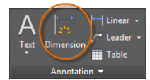
3. Dimensioning
Create several types of dimensions and save dimension settings by name
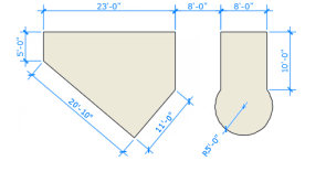
Linear Dimensions
horizontal, vertical, aligned, and radial dimensions can be created with the DIM command. The type of dimension depends on the object that is selected and the direction of dimension line.
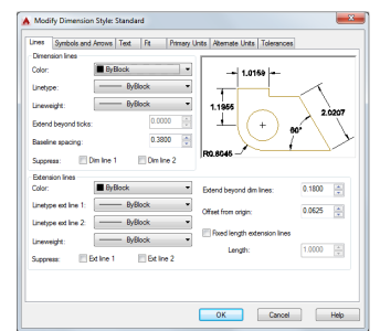
Dimension Styles
Dimension styles help establish and enforce drafting standards. There are many dimension variables that can be set with the DIMSTYLE command to control virtually every nuance of the appearance and behavior of dimensions. All these settings are stored in each dimension style. The default dimension style is named either Standard (imperial) or ISO-25 (metric). It is assigned to all dimensions until you set another style as the current dimension style. The current dimension style name, Hitchhiker in this case, is displayed in the drop-down list of the Annotation panel.
4. Object snap
Object snap provide a way to specify precise locations on objects whenever you are prompted for a point within a command. With running object snap(Osnap) settings, a snap point at an exact location on an object can be specified. When more than one option is selected, the selected snap modes are applied to return a point closest to the center of the aperture box.
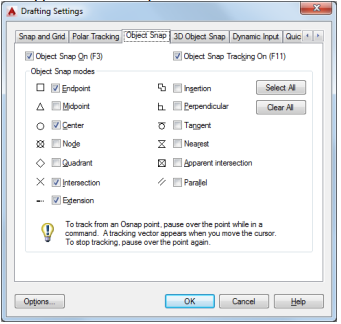
Object Snap ON (F3)
Turns running object snaps ON and OFF. The object snaps selected under Object Snap Modes
are active while the Osnap mode in ON.
Object Snap Tracking On (F11)
Turns object snap tracking ON and OFF. With object snap tracking, the cursor can track along
alignment paths based on other object snap points when specifying points in a command.
Object Snap Modes:
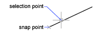
End Point
Snaps to the closest endpoint of an arc, elliptical arc, line, multiline, polyline segment, spline,
region or to the closest corner of a trace. Solid or 3D face.
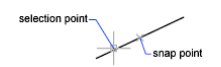
Midpoint
Snaps to the midpoint of an arc, ellipse, elliptical arc, line, multiline, polyline segment, region, solid, spline or xline.
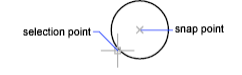
Center
Snaps to the center of an arc, circle, ellipse, or elliptical arc
Node
Snaps to a point object, dimension definition point, or dimension text origin.
Quadrant
Snaps to a quadrant point of an arc, circle, ellipse, or elliptical arc.
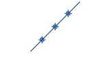
Intersection
Snaps to the intersection of an arc, circle, ellipse, line, multiline, polyline, spline, or xline and other geometrical objects. Extended intersections are not available as a running object snap.

Extension
It causes a temporary extension line or arc to be displayed when the cursor is passed over the
endpoint of objects, so that points can be specified on the extension.
Insertion
Snaps to the insertion point of an attribute, a block, a shape, or text.
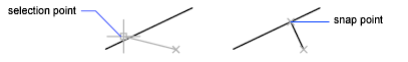
Perpendicular
Snaps to a point perpendicular to the selected geometric object.
Deferred Perpendicular snap mode is automatically turned on when the object you are drawing
requires that more than one perpendicular snap can be completed. An object such as a line, arc,
circle, polyline, ray, xline, multiline, or 3D solid edge as an object from which to draw a
perpendicular line can be used.
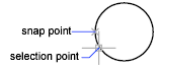
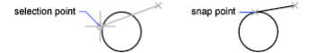
Tangent
Snaps to the tangent of an arc, circle, ellipse, elliptical arc, polyline arc, or spline. Deferred Tangent snap mode is automatically turned on when the object that is being drawn requires and complete more than one tangent snap. It can be used to draw a line or xline that is tangent to arcs, polyline arcs, or circles. When the cursor passes over a Deferred Tangent snap point, a marker and an AutoSnap tooltip are displayed.
Apparent Intersection
Snaps to the visual intersection of two objects that do not intersect in 3D space but may appear
to intersect in the current view.
Nearest
Snaps to the nearest point on an arc, circle, ellipse, elliptical arc, line, multiline, point, polyline,
ray, spline or xline.
Parallel
Constraints a line segment, polyline segment, ray or xline to be parallel to another linear object.
The parallel object snap is to be specified, after specifying the first point of a linear object.
Unlike other object snap modes, the cursor must be moved and hover over another linear object
until the angle is acquired. Then, move the cursor back toward the object that is to be created.
When the path of the object is parallel to the previous linear object, an alignment path is
displayed, which you can use to create the parallel object.
Select All
Turns on all running object snap modes.
Clear All
Turns off all running object snap modes.
5. Zoom
The objects viewed in the drawing area can be zoomed in or out, and moved to see different
portions of the sheet in detail by using the following commands:
The zoom flyout of standard tool bars has nine icons to opt.
a) Zoom window: This command enlarges a rectangular area of a drawing based on a defined
window using the cross hair
b) Zoom all: This command displays the are of the drawing limits or extent whichever are
greater.
c) Zoom dynamic: Pans and zooms using a rectangular view box.
d) Zoom scale: Zooms to change the magnification of a view using a scale factor.
e) Zoom center: Zooms to display a view defined by a center point and a magnification value
or a height.
f) Zoom Object: Zooms to display one or more selected objects as large as possible and in
the center of the view.
g) Real Time: Zooms interactively to change the magnification of the view.
h) Zoom extends: Zooms to display the maximum extents of all objects.
i) Zoom Previous: Zooms to display the previous view. You can restore up to 10 previous
views.
Out of these “Zoom window” and “Zoom all” command are more useful. Similarly, “Zoom real
time”, “Pan real time” and “Zoom previous” commands are also frequently applied for drafting.
Comments are closed.