1. Point:
The Point command will insert a point marker in your drawing at a position which you pick or at any coordinate location which you enter in the Command window. Other ways of defining a point can be accessed through the fly-out menu. The default point style is a simple dot, which is often difficult to see but you can change the point style to something more easily visible or elaborate using the point style dialogue box.

2. Line:
Creates a straight line segment. It is used to draw lines continuously. Each segment is a line
object that can be edited separately.
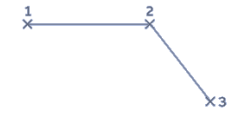
Continue: Continues a line from the endpoint of the most recently drawn line.
Close: End the line segment at the beginning of the first line segment, which forms a closed
loop of line segment.
Undo: Erases the most recent segment of a line sequence

3. Construction Line (XL):
The construction line (XLINE) command creates a line of infinite length which passes through
two picked points. Construction lines are very useful for creating construction frameworks or
grids. Construction lines are not normally used as objects in finished drawings. Therefore, it is
usual to draw all your construction lines on a separate layer which will be turned off or frozen
prior to printing.
Construction line options
· Hor: Creates a horizontal construction line.
· Ver: Creates a vertical construction line.
· Ang: Creates a construction line at a specified angle.
· Bisect: Create a construction line that bisects an angle defined by 3 points.
· Offset: Creates a construction line that is offset from an existing line by a specified
· distance.

4. Polyline (Pline):
The PLINE command differs from the LINE command in that the segments of the PLINE are
connected. When using the LINE command, each segment is its own object. When using
PLINE, all line segments are one object.

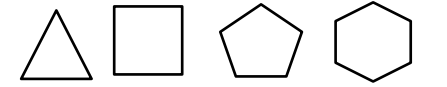
5. Polygon
A polygon of sides ranging from 3 to any number can be drawn using Polygon command. It
creates an equilateral closed polyline.
Centre of Polygon: Defines the center of the polygon.
Inscribed in Circle: Specifies the radius of a circle on which all vertices of the polygon line.
Circumscribe about circle: Specifies the distance from the centre of the polygon to the
midpoints of the edges of the polygons.
Edge: Defines a polygon by specifying the endpoints of the first edge
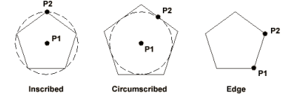
Specifying the radius with your pointing device determines the rotation and size of the polygon. Specifying the radius with a value draws the bottom edge of the polygon at the current snap rotation angle.

6. Arc
This command is used to draw an arc accurately. To create an arc, a combination of centre, endpoint, start point, radius, angle, chord length, and direction values can be specified. Arcs are drawn in a counter clockwise direction by default.
Start Point: Draws an arc

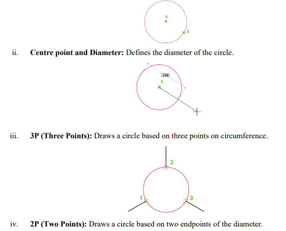
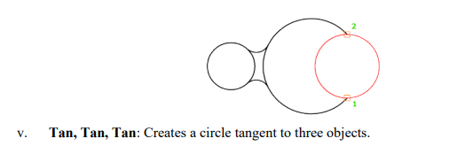
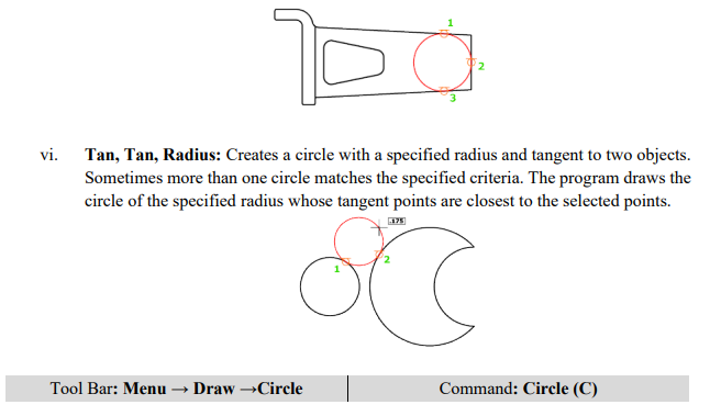
7. Circle
There are many ways to draw a circle, the default being the centre point of circle and radius.
Below are the possible ways of drawing the circle.

Ellipse
The Ellipse command gives you a number of different creation options. The default option is to pick the two end points of an axis and then a third point to define the eccentricity of the ellipse

8. Donut
The DONUT is a special type of polyline which is made up of arc segments. A DONUT has two properties: it has width, and it is closed. The width of DONUT is set by specifying inside and outside diameters. The inside diameter may be zero thereby making it a filled circle.
9. Hatch patterns
The HATCH command is used to fill up the area using a suitable pattern. The type of pattern and pattern variables can be chosen from a library of patterns available. The hatching will be carried out inside a closed defined area.

10. Text
Words, messages and numbers can be inserted as required on an engineering drawing. The alphanumeric keyboard is used extensively for non-graphical input such as text. The text style, height, text angle, aspect ratio, colour, etc. are some of the attributes associated with text. These attributes can be changed as per requirements.
11. Rectangle
Creates a rectangular polyline. With this command, the parameters (length, width, rotation) can be specified control the type of corners (fillet, chamfer, square).

Comments are closed.