A drawing describes the shape of an object. For complete details of an object, its size description
is also required. The information like distance between surfaces and edges with tolerance, location
of holes, machining symbols, surface finish, type of material, quantity, etc., is indicated on the
drawing by means of lines symbols, and holes. The process of furnishing this information on a
technical drawing as per a code of practice is called dimensioning.
Principles of dimensioning
1. Dimensioning should be done so completely that further calculation or assumption of any
dimension or direct measurement from the drawing is not necessary
2. Every dimension must be given, but none should be given more than once.
3. A dimension should be placed on the view where its use is shown more clearly.
4. Dimensions should be placed outside the views, unless they are clearer and more easily
read inside.
5. Mutual crossing of dimension lines and dimensioning between hidden lines should be
avoided. Dimension lines should not cross any other line of the drawing.
6. An outline or a centre line should never be used as a dimension line. A centre line may
extend to serve as an extension line
7. Aligned system of dimensioning is recommended.
Elements of dimensioning
1. Projection or extension Line
It is a thin continuous line drawn in extension of an outline. It extends by 3mm beyond the
dimension line.
2. Dimension Line
It is a thin continuous line terminated by arrowheads touching the outlines, extension lines or
centre lines.
3. Leader line
A leader line is a thin continuous line connecting a note or a dimension figure with the feature
to which it applies. One end of the leader line terminated either in an arrowhead or a dot. The
other end of the leader line is terminated in a horizontal line at a bottom level of the first or the
last letter of the note. It is always drawn at a convenient angle of not less than 300
to the line
which it touches.
4. Arrow head or Termination of dimension line
An arrow head is placed at each end of a dimensional line. Its pointed end touches an outline,
an extension line or a centre line. The size of an arrow head should be proportional to the thickness of the outlines. The length of the arrowhead should be three times its maximum width. Different types of arrowheads can be observed, but closed and filled type of arrowhead is widely used in engineering drawing.
Methods of indicating Dimensions
The two methods of indicating dimensions are:
1. Aligned
2. Unidirectional
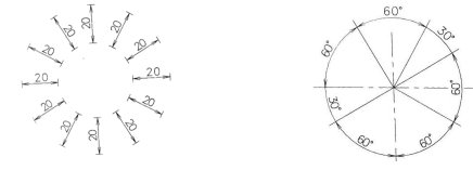
1. Aligned method
In this method, the dimension is placed perpendicular to the dimension line such a way that it
may be read from the bottom edge of the right-hand edge of the drawing sheet. The dimensions
must be placed in the middle and above the dimension line .
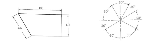
2. Unidirectional method
In unidirectional method, all the dimensions are placed in such a Way that they can be read from the bottom edge of the drawing sheet. The dimension lines are broken near the middle for inserting the dimensions. This is method is generally used on large drawings.
Arrangement of Dimension lines
The dimensions of an object can be placed according to either Aligned or Unidirectional methods,
but they are arranged in the followings ways and the selection depends on the design and the
construction requirements.
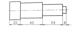
1. Chain dimensioning
This type of dimensioning is used only where the possible accumulation of tolerances does not endanger the functional requirements of the part.(fig. )
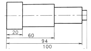
2. Parallel dimensioning
This type of dimensioning is used only where a number of dimensions of a part have common datum feature
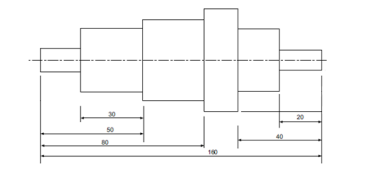
3. Combined dimensioning
In this a combination of both chain and parallel dimensioning are applied. But, the distance of dimension line from the object boundary or nearby dimensions line should be at least 5mm to 6mm
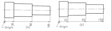
4. Superimposed running dimensioning
This type of dimensioning is a simple parallel dimensioning and may be used where there are space limitations and where no legibility problems will arise. In this, origin is to be indicated appropriately and the opposite end of each dimension line should be terminated only with arrow head.
5. Dimensioning by coordinates
This type of dimensioning follows the principle of coordinate system of identifying the points.
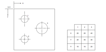
This type of dimensioning follows the principle of coordinate system of identifying the points. There are three ways of indicating this type of dimensioning
Comments are closed.