1. Go to the following website: https://www.autodesk.com/education/free-software/all
2. Click AutoCAD
3. Create your login account using the MRCET mail id. xyz@mrcet.ac.in (you can access the
software for 3 Years).
4. After you create your account, sign in and choose
a. Version: AutoCAD 2020
b. Operating System: 32 or 64 bit
(To find the information, Right click on My Computer or My PC and select properties.)
c. Language: English (so you can have more effective technical support)
5. Serial number and Product key will be displayed. This information is required at the time of
activation after installing the software.
6. Download can be carried in two ways:
a. Download Now (Recommended)
b. Browser Download
7. After downloading the file, double click on the installation file, and then click Yes to complete
the installation.
8. Now click on Install
9. Check the box I accept the click next
10. For the standalone License type default option, enter the serial key & product key details found
on the software database for this software version.
11. Click Install and the Click Finish to complete the installation.
System Requirements
· Operating System : 32 or 64-bit Microsoft Windows/ XP-professional/vista or more
· Processor : Pentium 4 or later
· RAM : 4GB or more
· Graphics Card : 1GB or more/ integrated graphics
· Hard Disk : 20GB free hard disk space available including installation
· Pointing devices : Mouse, digitizer with win tab drive, Keyboard
· DVD ROM : Any Speed (not mandatory)
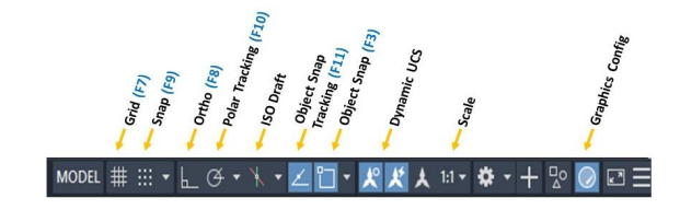
Function Keys
The keyboard function keys F1-F12 control settings that are commonly turned on and off as we
work in the product.
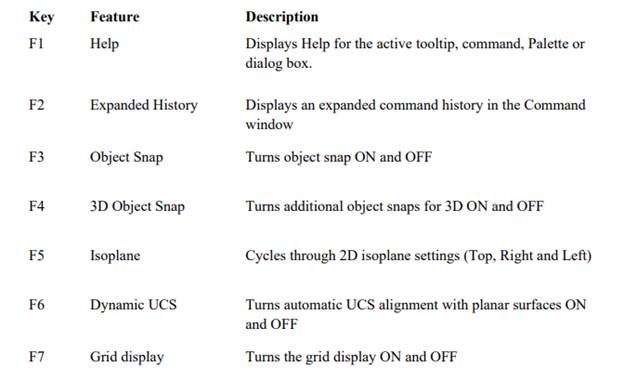
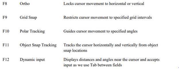
Note: F8 and F10 are mutually exclusive -turning one On will turn the other OFF.
User Interface
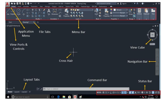
Application Menu
Menus are available through the application button in the upper left corner of the drawing window. This menu contains the commands used to create, save, print, and manage your drawing.
Command prompt
The rectangular horizontal window at lower side of the screen is called the command area. The
instructions given to the computer through keyboard is shown in this area. It important to read the
command prompt when working with an unfamiliar command.
To enter a command using the keyboard, type the command name on the command line and press
Enter or the Spacebar.
Navigation Bar
The navigation bar is a user interface element where you can access both unified and productspecific navigation tools. Unified navigation tools are those that can be found across many
Autodesk products. Product-specific navigation tools are unique to a product
Quick access toolbar
The Quick Access toolbar, displayed in the Drafting & Annotation workspace, is located at the very top of the drawing window next to the Application button. The Quick Access toolbar may be customized by adding or removing commands. This is done by right clicking on the toolbar and selecting Customize Quick Access toolbar or selecting the arrow at the end of the toolbar.

The Quick Access toolbar contains the following commands:
· QNew: Opens a new drawing.
· Open: Opens an existing drawing. (Ctrl+O)
· Save: Saves the current drawing. (Ctrl+S)
· Save as: Allows you to save the current drawing under a different name. (Ctrl+Shift+S)
· Plot: Plots or prints the current drawing. (Ctrl+P)
· Undo: Used to undo previous command or actions.
· Redo: Used to redo commands that have been undone.
Drawing area & Cross Hair
The rectangular large space between the pull-down menu bar and the command window is the
drawing area. The cursor moves moves in this area in the form of a cross hair as mouse is moved
by the user. The cross hair position is indicated by coordinate values shown at the left end of the
status bar.
View Cube
The View Cube is a navigation tool that allows you to switch between viewing directions. While
this is very useful in 3D space, it is not very useful in 2D space. It is located in the upper right
corner of the drawing area.
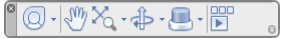
Status bar
The status bar displays the cursor location, drawing tools, and the tools that affect the drawing environment. It also provides quick access to some of the most commonly used drawing tools, Coordinates of the cross hair (Cursor) and we can toggle the settings such ads grid, snap, polar tracking and object snap.
Comments are closed.