Engineering Graphics
Engineering Graphics is the principal method of communication in the field of engineering and
science . the graphics of engineering design and construction is one among the most important
courses of all studies for engineering. It is the language used by the designer, technician and
engineer to communicate, design and construct details to others.
The Graphic Language
Engineering drawing is the graphic language used by engineers and technologists globally. The
graphic language may be defined as the graphic representation of physical objects and their
relationships. This language is written in the form of drawings using straight and curved lines
which represent the shape, size and specifications of physical objects. The language is read by
interpreting the drawings so that the physical objects can be constructed exactly as conceived by
the designer. An engineer, should have proper understanding of the theory of projection,
dimensioning and conventions related to working drawings, in order to become professionally
efficient.
Traditional Drafting
Engineering drawings are made up of straight and curved lines to represent the surfaces, edges and
centres of objects. Symbols, dimensional values and word-notes are added to these lines so that
they collectively make the complete description. The traditional drafting is the presentation of
these drawings manually, by freehand sketching or with the help of drawing instruments.
Computer Aided Drafting
Computer Aided Drafting is a process of preparing a drawing of an object on the screen of a
computer. There are various types of drawings in different fields of engineering and sciences. In
the fields of mechanical or aeronautical engineering, the drawings of machine components and the
layouts of them are prepared. In the field of civil engineering, plans and layouts of the buildings
are prepared. In the field of electrical engineering, the layouts of power distribution system are
prepared. In all fields of engineering use of computer is made for drawing and drafting.
The use of CAD process provides enhanced graphics capabilities which allows any designer to
· Conceptualize his ideas
· Modify the design very easily
· Perform animation
· Make design calculations
· Use colors, fonts and other aesthetic features
Benefits of CAD
The implementation of the CAD system provides variety of benefits to the industries in design and
production as given below:
1. Improved productivity in drafting
2. Shorter preparation time for drawing
3. Reduced man power requirement
4. Customer modifications in drawing are easier
5. More efficient operation in drafting
6. Low wastage in drafting
7. Minimized transcription errors in drawing
8. Improved accuracy of drawing
9. Assistance in preparation of documentation
10. Better designs can be evolved
11. Revisions are possible
12. Colours can be used to customize the product
13. Production of orthographic projections with dimensions and tolerances
14. Hatching of all sections with different filling patterns
15. Preparation of assembly or sub assembly drawings
16. Preparation of part list
17. Machining and tolerance symbols at the required surfaces
18. Hydraulic and pneumatic circuit diagrams with symbols
19. Printing can be done to any scale
CAD SOFTWARES
The software is an interpreter or translator which allows the user to perform specific type
of application or job related to CAD. The following softwares are available for drafting
1. AUTOCAD
2. CREO
3. CATIA
4. SOLID WORKS
5. NX Unigraphics
6. FUSION 360
7. INVENTOR
8. SOLID EDGE
The above software’s are used depending upon their application
Drawing Instruments and aids
Drawing Instruments are used to prepare drawings easily and accurately. A neat and clean drawing
is prepared by the help of good quality drawing instruments and other aids. The following are the
drawing aids commonly used in industries:
· Drawing board
· Setsquares
· French curves
· Templates
· Mini drafter
· Instrument box
· Protractor
· Set of scales
· Drawing sheets
· Pencils
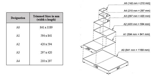
Drawing Sheet:
Engineering drawings are prepared on standard size drawing sheet. The correct shape and size of
the object can be visualized from the understanding of not only its views but also from the various
types of lines used, dimensions, notes, scales etc., The standard drawing sheet sizes are arrived at
on the basic Principal of X:Y =1: √2 and XY=1 where x and y are the sides of the sheet. For
example, AO, having a surface area of 1Sq.m; X=841mm and Y=1189mm.The successive sizes
are obtained by either by halving along the length or doubling the width, the area being in the
ratio1:2. Designation of sizes is given in the fig. For class work use of A2 size drawing sheet is
preferred.
Drawing Sheet Layout
It is an important function of engineering drawing. Also, it is very important to understand the standard for the selection of suitable scale, margin space, title block and part list etc., on the sheet. The below mentioned details in the drawing sheet is according to IS 46:2003
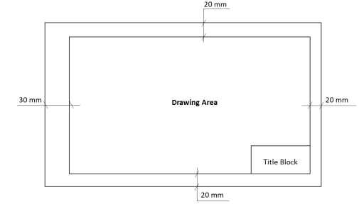
Title Block
Title block is to be placed within the drawing space at the bottom right hand corner of the drawing
sheet and it should be visible when prints are folded. It should consist of one or more adjoining
rectangles. These rectangles may be divided further into boxes for inserting specific information.
The size of the title block as recommended by the B.I.S. is 185 mm x 65 mm fro all designations
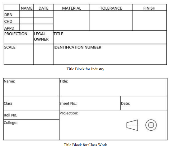
of the drawing sheets. All the title blocks should contain at least the particulars mentioned below.
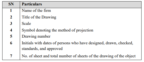
The Title blocks used in industries and for class work purpose are shown below.
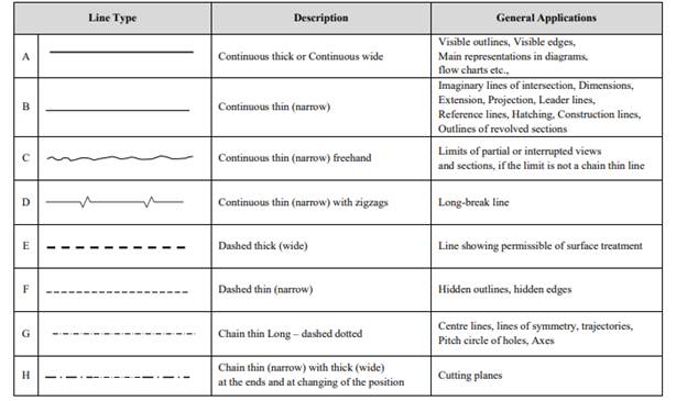
Types of Lines:
1. Outlines (A): Continuous thick or wide lines drawn to represent the visible edges and surface
boundaries of the objects are called Outlines or Principal Lines.
2. Margin Lines (A): They are continuous thick or wide lines along which the prints are trimmed
3. Dimension lines (B): these lines are continuous thin lines that are terminated at the outer ends
by pointed arrowheads touching the outlines, extension lines or centre lines.
4. Extension or Projection Lines (B): These are also continuous thin lines that extend by about 3
mm beyond the dimension lines.
5. Construction Lines (B): These continuous thin light lines used for constructing figures.
6. Hatching or Section Lines (B): These are the continuous thin lines generally drawn at an angle
of 450
to the main outline of the section and are uniformly spaced about 1mm to 2 mm apart.
These are used to make the section evident.
7. Leader or pointer lines (B): It is a continuous thin line drawn to connect a note with the feature
to which it applies.
8. Border Lines (B): Perfectly rectangular working space is determined by drawing the border
lines.
9. Short- break lines (C): These are continuous, thin and wavy lines drawn freehand and are used
to show a short break or irregular boundaries.
10. Long-break lines (D): These are thin ruled lines with short zigzags within them and are drawn
to show the long breaks.
11. Hidden or dotted lines (E/F): Interior or hidden edges and surfaces are shown by hidden lines.
They are also called as dotted lines.
12. Centre lines (G): These are thin, long, chain lines composed of alternately long and dot lines
drawn to indicate the axes of cylindrical, conical or spherical objects or details and also to
show the centres of circles and arcs.
13. Cutting-plane lines (H): The location of cutting plane is shown by this line. It is a long, thin,
chain line, thick at ends only
LETTERING
Lettering is defined as writing of titles, sub-titles, dimensions, and other important particulars on
a drawing.
To undertake production work of an engineering component as per the drawing, the size and other
details are indicated on the drawing. This is done in the form of notes and dimensions. Main
features of lettering consume more time. Lettering should be done freehand with speed. Practice
accompanied by continuous efforts would improve the lettering skill and style.
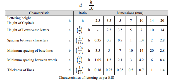
Size of Letters:
· Size of Letters is measured by the height h of the Capital Letters as well as numerals.
· Standard heights for Capital letters and numerals recommended by BIS are given below:
1.8, 2.5, 3.5, 5, 6, 10, 14, 20 mm
Note: Size of the letters may be selected based upon the size of the drawing.
Guide lines:
In order to obtain correct and uniform height of letters and numerals, guide lines are drawn using
2H pencil with light pressure. HB grade conical end pencil is used for lettering.
The following are some of the guidelines for lettering
· Drawing numbers, title block and letters denoting cutting planes, sections are written in
· 10mm size.
· Drawing title is written in 7 mm size.
· Hatching, subtitles, materials, dimensions, notes, etc., are written in 3.5mm size.
· Space between lines = 3/4h
· Space between words may be
Comments are closed.