AC motors are used worldwide in many applications to transform electrical energy into mechanical energy. There are many types of AC motors, but three phase AC induction motors, is the most common type of motor used in industrial applications. An AC motor of this type may be part of a pump or fan or connected to some other form of mechanical equipment such as a winder, conveyor, or mixer. The electric motor in its simplest terms is a converter of electrical energy to useful mechanical energy. The electric motor has played a leading role in the high productivity of modern industry, and it is therefore directly responsible for the high standard of living being enjoyed throughout the industrialized world.
AC motors provide the motive power to lift, shift, pump, drive, blow, drill, and perform a variety of other tasks in industrial, domestic, and commercial applications. The induction motor, the most versatile of the AC motors, has truly emerged as the prime mover in industry, powering machine tools, pumps, fans, compressors, and a variety of industrial equipments.
Fundamentals of three-phase AC motors
Three-phase AC motors are known as the ‘workhorses of industry’ because of their wide use and acceptance. They are popular because they are low in cost, compact in size, require less maintenance, withstand harsh industrial environments, etc. Three-phase AC motors are a class of motors that convert the three-phase electric power supplied at the input terminals, to mechanical power at the rotating shaft, through the action of a rotating magnetic field, produced by a distributed winding on the stator.
Three-phase AC motors are broadly classified as:
1. Induction motor
2. Synchronous motor
3. Wound rotor induction motor.
1. Induction motor
As the name implies, no voltage is applied to the rotor. The voltage is applied to the stator winding and when the current flows in the stator winding, a current is induced in the rotor by transformer action. The resulting rotor magnetic field will interact with the stator magnetic field, causing torque to exert on the rotor.
2. Synchronous motor
As the name suggests, rotor speed remains in synchronism with that of the stator magnetic field. The motor runs at the same speed. Unlike induction motors, synchronous motors are not self-starting. They have to be brought up to synchronous speed. Once they are locked then the rotor will continuously rotate.
3. Wound rotor induction motor
This motor has a ‘wire wound rotor’ from which three leads are brought out to the slip rings. It is possible to vary the rotor resistance. Introducing different resistances in the rotor circuit through the slip rings does this. The speed and the starting torque will now be variable.
Principle of operation of a induction motor
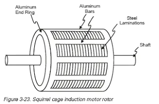
An electric motor’s principle of operation is based on the fact that a current-carrying conductor, when placed in a magnetic field, will have a force exerted on the conductor proportional to the current flowing in the conductor and to the strength of the magnetic field. In alternating current induction motors, the windings placed in the laminated stator core produce the magnetic field. The aluminum bars in the laminated rotor core are the current-carrying conductors upon which the force acts. The resultant action is the rotary motion of the rotor and shaft, which can then be coupled to various devices to be driven and produce the output.
FORCE & MOTION
Before discussing AC motors it is necessary to understand some of the basic terminology associated with motor operation. Force In simple terms, a force is a push or a pull. Force may be caused by electromagnetism, gravity, or a combination of physical means. Net Force Net force is the vector sum of all forces that act on an object, including friction and gravity. When forces are applied in the same direction, they are added. For example, if two 10 pound forces are applied in the same direction the net force would be 20 pounds.
TORQUE
Torque is a twisting or turning force that causes an object to rotate. For example, a force applied to the end of a lever causes a turning effect or torque at the pivot point. Torque (τ) is the product of force and radius (lever distance). τ = Force x Radius In the English system of measurements, torque is measured in pound-feet (lb-ft) or pound inches (lb-in). For example, if 10 lbs of force is applied to a lever 1 foot long, the resulting torque is 10 lb-ft.
SPEED
An object in motion takes time to travel any distance. Speed is the ratio of the distance traveled and the time it takes to travel the distance.
ANGULAR SPEED
The angular speed of a rotating object determines how long it takes for an object to rotate a specified angular distance. Angular speed is often expressed in revolutions per minute (RPM). For example, an object that makes ten complete revolutions in one minute, has a speed of 10 RPM.
INERTIA
Mechanical systems are subject to the law of inertia. The law of inertia states that an object will tend to remain in its current state of rest or motion unless acted upon by an external force. This property of resistance to acceleration/deceleration is referred to as the moment of inertia. The English system unit of measurement for inertia is pound-feet squared (lb-ft2).
FRICTION
Friction occurs when objects contact one another. As we all know, when we try to move one object across the surface of another object, friction increases the force we must apply. Friction is one of the most significant causes of energy loss in a machine.
WORK
Whenever a force causes motion, work is accomplished. Work can be calculated simply by multiplying the force that causes the motion times the distance the force is applied. Work = Force x Distance Since work is the product of force times the distance applied, work can be expressed in any compound unit of force times distance. For example, in physics, work is commonly expressed in joules. 1 joule is equal to 1 newton-meter, a force of 1 newton for a distance of 1 meter. In the English system of measurements, work is often expressed in foot-pounds (ft-lb), where 1 ft-lb equals 1 foot times 1 pound
POWER
Another often used quantity is power. Power is the rate of doing work or the amount of work done in a period of time.
HORSEPOWER
Power can be expressed in foot-pounds per second, but is often expressed in horsepower. This unit was defined in the 18 th century by James Watt. Watt sold steam engines and was asked how many horses one steam engine would replace. He had horses walk around a wheel that would lift a weight. He found that a horse would average about 550 foot-pounds of work per second. Therefore, one horsepower is equal to 550 foot-pounds per second or 33,000 foot-pounds per minute.
KILOWATTS
AC motors manufactured in the United States are generally rated in horsepower, but motors manufactured in many other countries are generally rated in kilowatts (kW). Fortunately it is easy to convert between these units
Horsepower=1.341 * kilowatts
CONSTRUCTION
Three-phase AC induction motors are commonly used in industrial applications. This type of motor has three main parts, rotor, stator, and enclosure. The stator and rotor do the work, and the enclosure protects the stator and rotor.
The stator is the stationary part of the motor’s electromagnetic circuit. The stator core is made up of many thin metal sheets, called laminations. Laminations are used to reduce energy loses that would result if a solid core were used. Stator laminations are stacked together forming a hollow cylinder. Coils of insulated wire are inserted into slots of the stator core,
The rotor is the rotating part of the motor’s electromagnetic circuit. The most common type of rotor used in a three phase induction motor is a squirrel cage rotor. Other types of rotor construction is discussed later in the course. The squirrel cage rotor is so called because its construction is reminiscent of the rotating exercise wheels found in some pet cages
ENCLOSURE
The enclosure consists of a frame (or yoke) and two end brackets (or bearing housings). The stator is mounted inside the frame. The rotor fits inside the stator with a slight air gap separating it from the stator. There is no direct physical connection between the rotor and the stator.
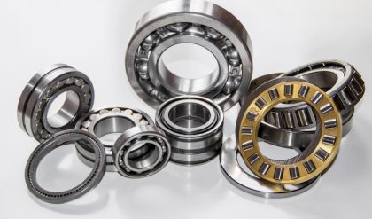
BEARING
Bearings, mounted on the shaft, support the rotor and allow it to turn. Some motors also use a fan mounted on the rotor shaft, to cool the motor when the shaft is rotating.
MOTOR SPECIFICATIONS (Important Nameplate Data)
• Catalog number.
• Motor model number.
• Frame.
• Type (classification varies from manufacturer to manufacturer).
• Phase – single, three or direct current.
• HP – horsepower at rated full load speed.
• HZ – frequency in cycles per second. Usually 60 hz in United States,
50 hz overseas.
• RPM – revolutions per minute.
• Voltage.
• Amperage (F.L.A.) – full load motor current.
• Maximum ambient temperature in centigrade – usually +40°C (104°F).
• Duty – most motors are rated continuous. Some applications,
however, may use motors designed for intermittent, special, 15, 30 or
60 minute duty.
• NEMA electrical design – B, C and D are most common. Design letter
represents the torque characteristics of the motor.
• Insulation class – standard insulation classes are B, F, and H. NEMA has
established safe maximum operating temperatures for motors. This
maximum temperature is the sum of the maximum ambient and
maximum rise at maximum ambient.
• Code – indicates locked rotor kVA per horsepower.
• Service factor – a measure of continuous overload capacity.
Electrical Characteristics and Connections
Voltage, frequency and phase of power supply should be consistent with the motor nameplate rating. A motor will operate satisfactorily on voltage within 10% of nameplate value, or frequency within 5%, or combined voltage and frequency variation not to exceed 10%.
Voltage
Common 60 hz voltages for single-phase motors are 115 volt, 230 volt, and
115/230 volt. Common 60 hz voltage for three-phase motors are 230 volt, 460 volt and 230/460 volt.
Phase
Single-phase motors account for up to 80% of the motors used in the United States but are used mostly in homes and in auxiliary low-horsepower industrial applications such as fans and on farms.
Three-phase motors are generally used on larger commercial and industrial equipment.
Speeds
The approximate RPM at rated load for small and medium motors operating at 60 hz and 50 hz at rated volts are as follows:
60 hz 50 hz Synch. Speed
2 Pole 3450 2850 3600
4 Pole 1725 1425 1800
6 Pole 1140 950 1200
8 Pole 850 700 900
Synchronous speed (no-load) can be determined by this formula:
Frequency (Hertz) x 120 / Number of Poles
Insulation Class
Insulation systems are rated by standard NEMA classifications according to maximum allowable operating temperatures. They are as follows:
Class Maximum Allowed Temperature*
A 105°C (221°F)
B 130°C (266°F)
F 155°C (311°F)
H 180°C (356°F)
* Motor temperature rise plus maximum ambient
Generally, replace a motor with one having an equal or higher insulation class. Replacement with one of lower temperature rating could result in premature failure of the motor. Each 10°C rise above these ratings can reduce the motor’s service life by one half.
Service Factor
The service factor (SF) is a measure of continuous overload capacity at which a motor can operate without overload or damage, provided the other design parameters such as rated voltage, frequency and ambient temperature are within norms. Example: a 3/4 HP motor with a 1.15 SF can operate at .86 HP, (.75 HP x 1.15 = .862 HP) without overheating or otherwise damaging the motor if rated voltage and frequency are supplied at the motor’s leads.

