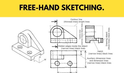
The hidden or internal parts of an object are shown by sectional views in technical drawings. The sectional view of an object is obtained by cutting through the object by a Suitable plane known as the section plane or cutting plane and removing the portion lying between the plane and the observer. The surface produced by cutting the object is called the section and its projection is called a sectional plan or sectional elevation. The section is indicated by thin section lines uniformly spaced and inclined at 45°.
A sectional view of an object is obtained by projecting the retained portion of the Jet which is left behind when object is cut by an imaginary section plane and the portion the object between the section plane and the observer is assumed as removed.
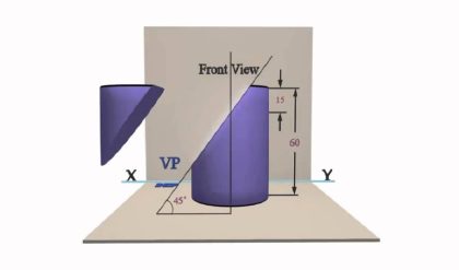
The object is cut by a section plane AA. The front half of the object between the Section plane and the observer are removed. The view of the retained portion of the object is projection VP. The top view is projected for the whole uncut object.

Types of sectional views of solids:
By using the five different types of perpendicular section planes we .obtain the following five types of sectional views of solids:
1. Section of solids obtained by horizontal planes.


